
RYLR330
LoRaWAN Gateway Mini PCIe Card
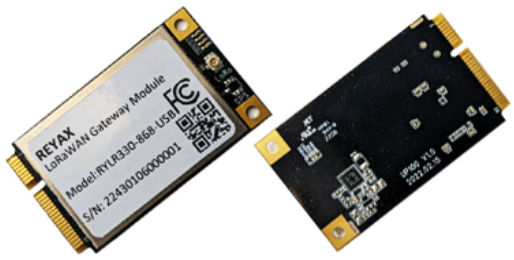
- Designed based on Mini-PCIe form factor 30mm x 59.95mm
- Tx power up to 26dBm, Rx sensitivity down to -139dBm@SF12, BW 125KHz
- Supports global license-free frequency band (US915, AS923, AU915, KR920, IN865, EU868)
- Supports optional USB/SPI interfaces
- Support Listen Before Talk
- SX1302 baseband processor emulates 8 x 8 channel LoRa packet detectors, 8 x SF5-SF12 LoRa demodulators, 8 x SF5-SF10 LoRa demodulators, one 125/250/500 KHz high-speed LoRa demodulator, and one (G)FSK demodulator
Description
The RYLR330 is a LoRaWAN Gateway Module with Mini-PCIe form factor based on Semtech SX1302/SX1303, SX1250 and SX1261 for Listen Before Talk feature, which enables easy integration into an existing router or other network equipment with LPWAN Gateway capabilities. It can be used in any embedded platform offering a free Mini-PCIe slot with USB/SPI connection. Furthermore, GPS chip and Crypto Co-processor are integrated onboard. This RYLR330 is a complete and cost-efficient gateway solution offering up to 10 programmable parallel demodulation paths, 8 x 8 channel LoRa packet detectors, 8 x SF5-SF12 LoRa demodulators, and 8 x SF5-SF10 LoRa demodulators. It is capable of detecting an uninterrupted combination of pockets at 8 different spreading factors and 10 channels with continuous demodulation of up to 16 packets
RYLR330
Specification
Operating Frequencies
The board supports the following LoRaWAN frequency channels, allowing easy configuration while building the firmware from the source code.
| Region | Frequency (MHz) |
| North America | US915 |
| Asia | AS923 |
| Australia | AU915 |
| Korea | KR920 |
| Europe | EU868 |
RF Characteristics
The following table gives typically sensitivity level of the UP100 gateway module.
| Signal bandwidth (KHz) | Spreading factor | Sensitivity (dBm) |
| 125 | 12 | -139 |
| 125 | 7 | -125 |
| 250 | 12 | -136 |
| 250 | 7 | -123 |
| 500 | 12 | -134 |
| 500 | 7 | -120 |
Electrical Requirements
Stressing the device above one or more of the ratings listed in the Absolute Maximum Rating section may cause permanent damage. These are stress ratings only. Operating the module at these or any conditions other than those specified in the Operating Conditions sections of the specification should be avoided. Exposure to Absolute Maximum Rating conditions for extended periods may affect device reliability. The operating condition range defines those limits within which the functionality of the device is guaranteed. Where application information is given, it is advisory only and does not form part of the specification.
Absolute Maximum Rating
The limiting values given below are following the Absolute Maximum Rating System (IEC 134).
| Symbol | Description | Condition | Min | Max |
| Operation Voltage | +2.7 | +3.3 | +5 | V |
| Current | 10 | 15 | mA | |
| Center Frequency | 1561±2.046 | MHz | ||
| Center Frequency | 1575.42±1.023 | MHz | ||
| Center Frequency | 1602±8 | MHz | ||
| Center Frequency | 1176 ±10 | MHz | ||
| Antenna Impedance | c | Ω | ||
| Polarization | ||||
| LNA Gain | 24 | 30.5 | dB | |
| Antenna Gain | 0 | 3.5 | dB | |
| Noise Figure | 1 | dB | ||
| V.S.W.R | 2 |
WARNING:
The product is not protected against overvoltage or reversed voltages. If necessary, voltage spikes exceeding the power supply voltage specification, given in table above, must be limited to values within the specified boundaries by using appropriate protection devices
Maximum ESD
| Parameter | Min. | Typ | Max. | Remarks |
| ESD_HBM | 1000V | Charged Device Model JESD22-C101 CLASS III | ||
| ESD_CDM | 1000V | Charged Device Model JESD22-C101 CLASS III |
NOTE:
Although this module is designed to be as robust as possible, electrostatic discharge (ESD) can damage this module. This module must be protected at all times from ESD when handling or transporting. Static charges may easily produce potentials of several kilovolts on the human body or equipment, which can discharge without detection. Industry-standard ESD handling precautions should be used at all times.
Power Consumption
| Version | Mode | Condition | Max. |
| SPI Version | Active mode (TX) | The power of the TX channel is 26dBm and 3.3V supply | 410mA |
| Active mode (RX) | TX disabled and RX enabled | 45mA | |
| USB Version | Active mode (TX) | The power of the TX channel is 26dBm and 3.3V supply. | 443mA |
| Active mode (RX) | TX disabled and RX enabled | 60mA |
Power Supply Range
Input voltage at 3V3 must be above the normal operating range minimum limit to switch on the module.
| Symbol | Parameter | Min | Typical | Max |
| 3V3 | Module supply operating input voltage | 3V | 3.3V | 3.6V |