
Migatron PD6000
PD6000

Features
- 1/8 DIN Digital Panel Meter with NEMA 4X, IP65 Front
- Input Power: 85-265 VAC
- Transmitter Power Supply: Isolated 24 VDC @ 200 mA
- 4 Relays with Interlocking Capability
- Field Selectable Inputs: 0-20 mA, 4-20 mA, 0-5 V, 1-5 V, and 0-10 V
- UL & C-UL Listed, 508 Industrial Control Equipment
About the PD6000
Migatron's PD6000 front, back and in between, Migatron's ProVu Meter boasts specifications, features and functionality that make it the only 1/8 DIN process meter you will ever need. One of features that makes the ProVu such a useful device is its built-in 24 VDC power supply to drive the transmitter. This feature not only saves the cost of an external power supply, but also greatly simplifies wiring. In addition, there is a second 40 mA power supply provided with the 4-20 mA output option.
NEMA 4X rated front panel which means you can install the ProVu in panels exposed to moisture, dust and other adverse conditions. 6-digit dual-line display that can display numbers up to 999,999 on the upper line and show either a tag or the input in a different scale on the lower line.
Other key features include four relays and 4-20 mA output option, advanced signal input conditioning like automatic round signal input conditioning like automatic round horizontal tank linearization, function keys, pump alternation capability, and Modbus RTU serial communications. Finally all these features and capabilities can easily be programmed with free MeterView Pro PC-based software.
Specifications
| Relay Specifications | |
|---|---|
| Rating | 4 SPDT (Form C) internal external; rated 3 A @ 30 VDC and 125/250 VAC resistive load; 1/14 HP (= 50 watts) @ 125/250 VAC for inductive loads such as contractors, solenoids, etc. |
| Noise Suppression | Noise suppression is recommended for each relay contact switching inductive loads |
| Deadband | 0-100% of span, user programmable |
| High or Low Alarm | User may program any alarm for high or low trip point. Unused alarm LEDs and relays may be disabled (turned off) |
| Relay Operation | Automatic (non-latching), latching (re-quires manual acknowledge) with/without clear, sampling (based on time), pump alternation control (2 to 8 relays), Off (disable unused relays and enable interlock feature, manual on/off control mode). |
| Relay Reset | User selectable via front panel buttons or digital inputs |
| Time Delay | 0 to 999.9 seconds, on & off relay time delays. Programmable and independent for each relay. |
| Fail-Safe Operation | Programmable and independent for each relay. Note: Relay coil is energized in non-alarm condition. In case of power failure, relay will go to alarm state. |
| Auto Initialization | When power is applied to the meter, relays will reflect the state of the input to the meter. |
| Process Input Specifications | |
|---|---|
| Inputs | Field selectable : 0-20, 4-20mA, +/- 10V (0-5, 1-5, 0-10V), Modbus PV (salve) |
| Isolated Transmitter Power Supply | Terminals P+ & P- : 24VDC +/- 10% rated @ 200 mA max |
| Accuracy | +/- 0.03% of calibrated span +/- count, square root & programmable exponent accuracy range : 10-100% of calibrated span |
| Temperature Drift | 0.005% of calibrated span/°C max from 0 to 65°C ambient, 0.01% of calibrated span/°C max from -40 to 0°C ambient. |
| Signal Input Conditioning | Linear, square root, program-mable exponent, or round horizontal tank volume calculation. |
| Multi-Point Linearization | 2 to 32 points for PV or PV1. 2 to 8 points for PV2 (Dual-Scale Level feature) Programmable Exponent: 1.0001 to 2.9999 |
| Calibration Range | 4-20 mA: minimum span input 1 & input 2: 0.15 mA. ±10 V: minimum span input 1 & 2: 0.10 V. An Error message will appear if input 1 and input 2 signals are too close together |
| Input Impedance | Voltage ranges: greater than 500 kΩ. Current ranges: 50 - 100 Ω (depending on resettable fuse impedance). |
| Input Overload | Current input protected by resettable fuse, 30 VDC max. Fuse resets automatically after fault is removed |
| General Specifications | |
|---|---|
| Except where noted all specifications apply to operation at +25°C. | |
| Power Input | 85-265 VAC 50/60 Hz, 90-265 VDC, 20 W max. Powered over USB for configuration only. |
| Fuse | Required external fuse: UL Recognized, 5 A max, slow blow; up to 6 meters may share one 5 A fuse. |
| Environmental | Operating temperature range: -40 to 65°C Storage temperature range: -40 to 85°C Relative Humidity: 0 to 90% non-condensing |
| Front Panel | NEMA 4X, IP65 |
| Connections | Removable screw terminal blocks accept 12 to 22 AWG wire. |
| Tightening Torque | Screw terminal connectors: 5 lb-in (0.56 Nm) |
| Weight | 9.5 oz (269 g) |
| Enclosure | 1/8 DIN, high impact plastic, UL 94V-0, color: black |
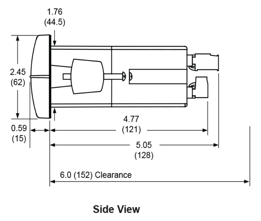
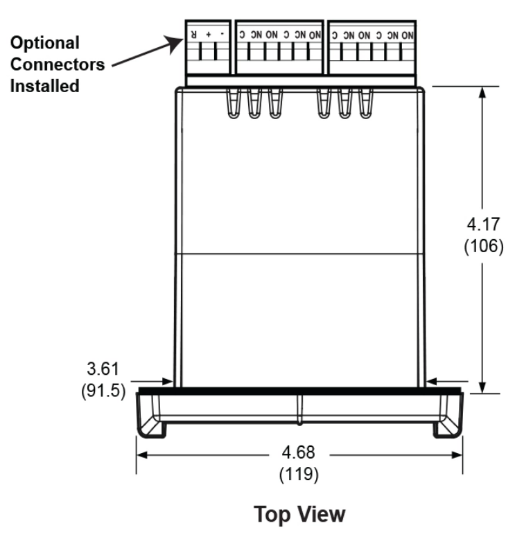
| Mounting | 1/8 DIN panel cutout required: 3.622” x 1.772” (92 mm x 45 mm). Two panel mounting bracket assemblies are provided |
| Overall Dimensions | 4.68” x 2.45” x 5.64” (119 mm x 62 mm x 143 mm) (W x H x D) |
| Display | Upper display: 0.60” (15 mm) high. Lower display: 0.46” (12 mm) high. Both are 6 digits (-99999 to 999999), red LEDs. |
| Display Update Rate | 5/second (200 ms) |
| Display Assignment | The upper and lower displays may be assigned to PV1, PV2, PCT (percent), d r-u, d gross, d nt-g, max/ min, alternate max & min, set points, units (lower display only), or Modbus input. |
| Max/Min Display | Max / min readings reached by the process are stored until reset by the user or until power to the meter is turned off. |
| Programming Methods | Four front panel buttons, digital inputs, PC and MeterView Pro software, Modbus registers |
| UL File Number | UL & C-UL Listed. E160849; 508 Industrial Control Equipment |


Ordering Information
| Part Number | Output / Description |
|---|---|
| PD6000-6R4 | 1/8 DIN ProVu Digital Panel Meter with 4 Relays |