
CSS CANmod.input
8 Analog, Digital, Pulse to CANBus Converter

This sensor-to-CAN module produces analog, digital and pulse measurements from 8 input channels and outputs the data via CAN bus. The module is 100% standalone, no PC required.
The compact device offers pro specs include high accuracy and high frequency sampling as well as configurable input ranges and digital thresholds.
The module integrates with any CANbus to provide data for ECUs or CAN tools. Example, you can use the module as an add-on for the CANedge.

Connect analog sensors
Sensors that produce analog outputs include force/pressure (load cells), current, distance (ultrasonic, laser, lidar, infrared), rotation (potentiometers), temperature, hall effect, magnometers, humidity, sound, atmospheric pressure, acceleration, gyroscopes - and many more.

Connect digital sensors
Sensors with digital outputs include hall effect switches, buttons (for e.g. registering events), reed switches (e.g. for door/valve/latch position registration), resistance-to-digital (RTD) sensors and more. Many sensors with analog outputs also produce optional digital outputs.

Connect pulse sensors (frequency, counter)
Sensors with pulse-oriented outputs include rotational speed sensors (e.g. hall effect frequency sensors), rotational position sensors, buttons & toggle switches (event counters), frequency meters and sensors producing e.g. Pulse Width Modulation (PWM) outputs.

Easy add Analog, Digital, Pulse Data to any CANBus System
Add analog, digital, pulse data via 8 input channels to your CAN bus, e.g. for use by ECUs or CAN hardware.
- Powerful parallel sampling of analog, digital, pulse signals
- Configure input range for optimal resolution, amplification
- Configure digital high, low levels include optional hysteresis
- Quickly connect sensors via optional DB25 input adapter cable
- Optional output signals via CAN FD for fewer frames
- Daisy chain multiple modules for 16, 24, 32, … channels
- Dedicated excitation signal for powering input sensors (~3.3 V)
- Power device at 5-26 V DC via standard DB9 adapter cables
- Optional record the data via any CAN interface, logger
- DBC file included for easy decoding to human readable form

CSS CANmod.input module lets you connect up to 8 analog, digital or pulse type sensors - and output the sensor data via configurable CSS CAN frames into any CSS CAN bus 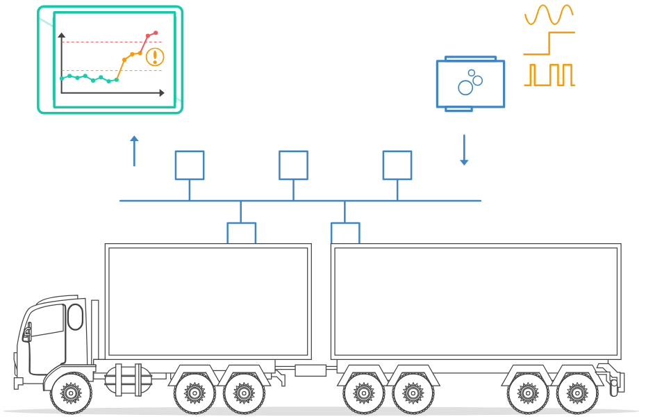
Customers can install the CSS CANmod.input 'standalone' in any CSS CAN system (cars, trucks, ships, …) to inject configurable CSS CAN frames with input sensor data into the existing CSS CAN traffic 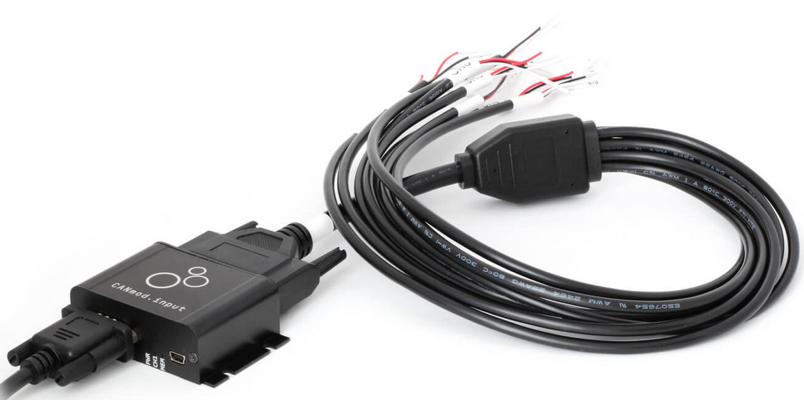
Optional CSS DB25-input adapter cable enables plug & play connection of a variety of sensors via open wires for each channel (insulated via heatshrinked pin headers) 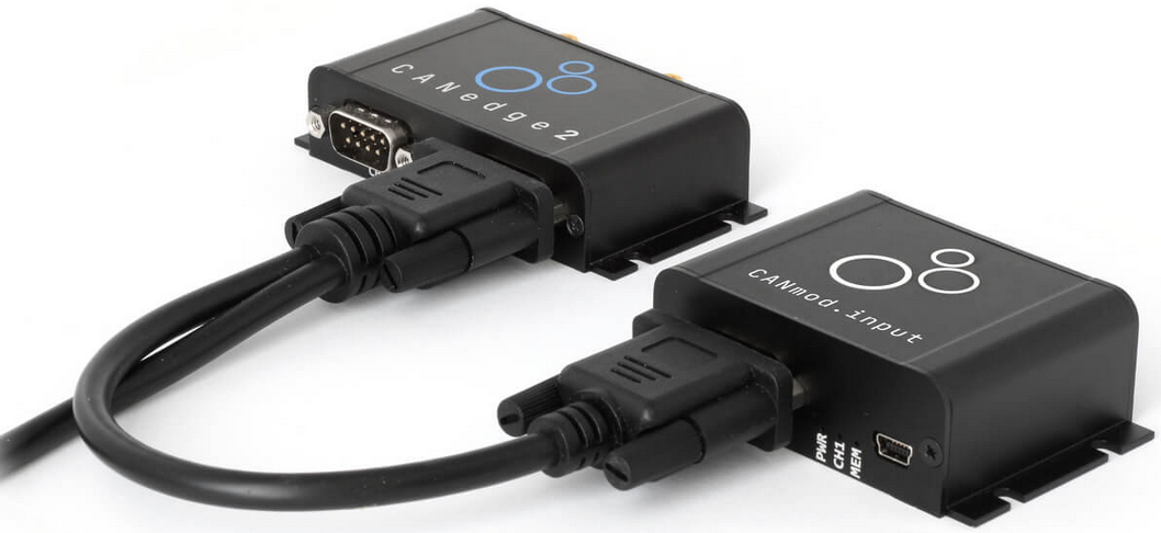
CSS CANmod.input module can e.g. be used as a plug & play add-on for the CSS CANedge (powered via 2nd port) - letting you combine CSS CAN/LIN data with timesynced analog/digital/pulse data 
Customers can also log 2 x CSS CAN/LIN with a CSS CANedge along with data from the CSS CANmod.input, by e.g. utilizing a CSS DB9 Y-splitter to connect both devices to one of the bus networks 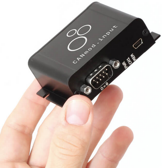
CSS CANmod.input offers vast functionality and pro specs - yet it is extremely compact, measuring only 7 x 2 x 5 CM and weighing just 70 G 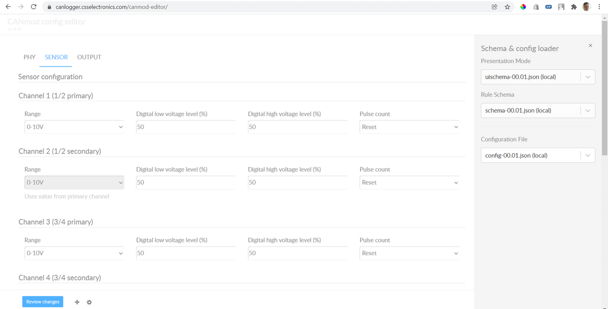
CSS CANmod.input can be configured via the USB connector using our online/offline config editor tool (or a simple JSON text editor) 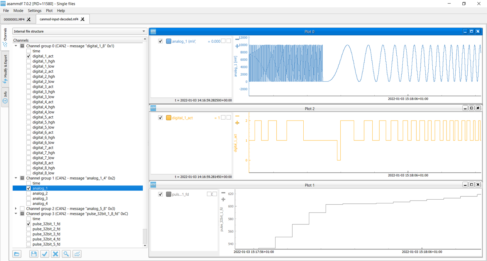
CSS CANmod.input measures both the analog, digital and pulse signal of every channel, enabling powerful analyses and high flexibility (picture from the asammdf GUI) 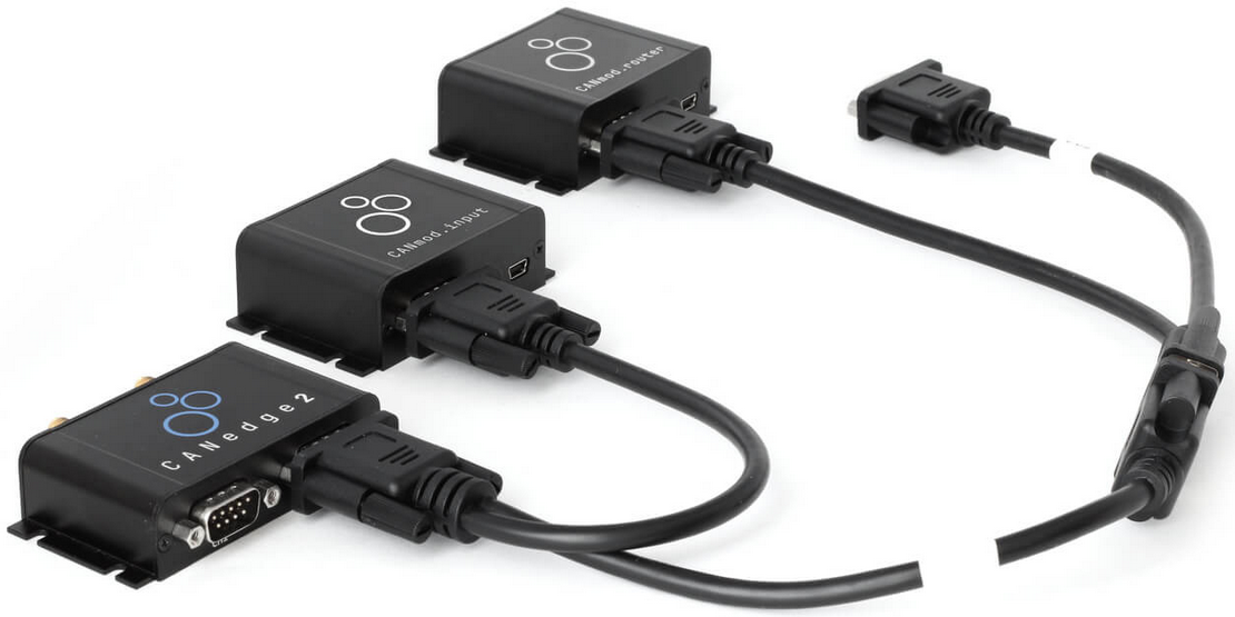
Customers can easily mix and daisy chain multiple CSS CANmod modules, thus adding different sensor types and/or more channels

Log, Stream Sensor Data
CSS CANmod.input is often used as an 'add-on' for the CANedge. This setup lets you record e.g. vehicle data via Channel 1 and analog/digital/pulse data via Channel 2. The data can be easily DBC decoded via e.g. the asammdf GUI, Python or MATLAB.
You can also stream the sensor data in realtime via USB using SavvyCAN to view raw/decoded data (e.g. via plots), ideal for validating your setup pre-deployment or for lab testing.
Technical Specifications
| General | |
|---|---|
| Functionality | The device produces analog/ digital/ pulse measurements from 8 input channels and outputs signals via CAN |
| Included | CANmod.input module and USB dust cover (input sensors and mini USB adapter not included) |
| Firmware | Supports free firmware updates via USB for adding features |
| Configuration | Configuration files based on the popular open source JSON schema concept (similar to the CANedge) |
| Software | Free open source editor tool for easy device configuration (offline/ online version available) |
| Safety | CE, FCC, IC and RoHS certified (see the Docs for certificates) |
| Warranty | 1-year warranty |
| Support | Free, fast & high quality support |
| Support period | Security updates & vulnerability handling for min. 5 years from purchase (EU CRA) |
| Origin | Denmark |
| Sensor (Input) | |
|---|---|
| Channels | Supports 8 input channels |
| Sensor Types | All 8 input channels support analog, digital and pulse-type sensors |
| Sampling Method | Each input channel samples both the analog, digital and pulse signal of the connected sensor |
| Input Range | Configurable input ranges (0-10V, 0-5V, 0-2.5V, 0-1.5V, 0-0.625V) |
| Range modification is useful e.g. for optimizing quantization resolution and signal amplification | |
| The input channels share input ranges in pairs two (CH1/ CH2, CH3/ CH4, CH5/ CH6, CH7/ CH8) | |
| Resolution | 10 bit |
| Sampling Frequency | Analog inputs: 1kHz / Digital: 1 kHz / Pulse (frequency/ counter): 16 kHz |
| Digital Thresholds | Configurable digital high/ low switch thresholds (0-100%) incl. optional dead-zone/ hysteresis |
| Pulse Modes | Pulse inputs can be measured as frequencies (reset) or counters (accumulate) |
| Pulse Resolution | Up to 32 bit (4,294,967,294) |
| Protection | Sensor inputs are protected against overvoltage & undervoltage conditions |
| Input Impedance | 136K |
| Data Parameters | |
|---|---|
| CAN Signals | The module outputs sensor data via CAN messages/ signals (for a full list, see the Docs or DBC file) |
| Analog measurements are output in millivolt (mV) [1000 Hz] | |
| Digital measurements are output as 'actual' (dead-zone, low, high) and 'low/ high' signals [1000 Hz] | |
| Pulse measurements are output as frequency/ counter value (for reset/ accumulate mode) [1000 Hz] | |
| Note: Limits apply to the practical output frequency depending on baud rate, message count etc. |
| CAN Bus | |
|---|---|
| Channels | 1 x CAN channel |
| Modes | The device can either broadcast the data onto the CAN bus - or provide it on-request |
| Standard | ISO 11898: Compliant with CAN (between 5K and 1Mbit/s baud rates) and CAN FD (1M, 2M, 4M) |
| Identifiers | Compliant with CAN specifications 2.0A (11-Bit ID) and 2.0B (29-Bit ID) |
| Termination | Termination can be toggled via switch below DB9 connector |
| Retransmission | Retransmission of frames that have lost arbitration or been disturbed by errors |
| Transceiver Protection | Protection: +/- 25kV HBM ESD, +/- 12kV IEC ESD, +/- 14V bus fault, short circuit |
| Common mode input voltage: +/- 12V | |
| TXD dominant timeout (prevents network blocking in the event of a failure |
| Configuration | |
|---|---|
| Bit Rate | Select between standard bit rates (5K to 1M) or use custom bit-timing |
| Enable/ Disable | Individually enable/ disable each CAN message |
| Identifier Customization | Individually configure each CAN ID (11-bit or 29-bit) |
| Push/ Poll Mode | Individually configure 'trigger' modes for each CAN message (push or poll) |
| Frequency | Individually configure prescaling of each CAN message frequency to lower rates |
| Electrical | |
|---|---|
| Input Supply | +5V to +26V DC via the DB9 connector (power via pin 1 or pin 9) Alternatively power via USB (for updating firmware/config or for streaming data in real-time) |
| Power Consumption | Extremely low (<1W) - no risk of battery drainage |
| Protection | Reverse voltage protection on CAN-bus supply |
| Transient voltage event protection on supply lines |
| Mechanical | |
|---|---|
| Enclosure & Weight | Compact aluminium enclosure: 65 x 48 x 24 mm (L x W x H, excl. flanges/connectors), 70 grams |
| Connector (Front) | 1 x Standard D-Sub 9 (DB9) connector |
| Connector (Back) | 1 x D-Sub 25 (DB25) connector |
| Sensor Supply | Dedicated excitation signals for each channel (~3.3 V, shared max of 100 mA) |
| Pin-Out | See the product manual for the DB9/DB25 connector pin-outs |
| USB | Standard mini USB connector for config/ firmware updates and streaming (USB cable not included) |
| LEDs | Module status via 8 external LEDs: Power, CAN bus, Memory, CH/ CH2, CH3/ CH4, CH5/ CH6, CH7/ CH8 |
| Temperature | Operating temperature (CANmod.input module): -25degC to +70degC |
| IP Rating | IP Rating 40 |
| Mounting | Module can be mounted via e.g. velcro strips |